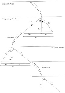
The compressor is a mechanical device which compress the air into high pressure. In the jet engine, compressor devided by two kind, they are compressors which direction of flow in the direction of the axial axis called axial flow compressor and a compressor which direction of flow perpendicular to the axis of the compressor called centrifugal compressor.
The axial flow compressor compresses its working fluid by first accelerating the fluid and then diffusing it to obtain a pressure increase. The fluid is accelerated by a row of rotating airfoils (blades) called the rotor, and then diffused in a row of stationary blades (the stator). The diffusion in the stator converts the velocity increase gained in the rotor to a pressure increase.
Design Proces.
Note: Just designing the compressor which in terms of aerodynamics and thermodynamics. Not discuss of the losses on certain parts.
The steps to design a axial flow compressor is as follows:
- Consider mass flow rate (m dot), pressure ratio, axial velocity (c).
- Calculate number of stage (N).
In this step, calculate temperature rise every stage by using velocity triangle, and then calculate temperature rise through the compressor.
How to find temperature rise every stage, follow steps bellow:
Triangle Velocity
First, find the entry angle of rotor (beta 1) using this equation.
where, (phi = 3.14).
After that, find then outlet angle of rotor (beta 2) using equation below.
,
Note: de Haller Number for rotor should not be more than 0.72 and for stator more than alpha 1.
Next step, find the temperature rise every stage using this equation.
Where,is Work done factor
Cpa is the specific heat capacity of air at constant pressure.
After you find the temperature rise every stage, find the temperature rise through the compressor.
.
Whereis ratio of specific heat of air,
andis pressure ratio.
.
To find number of stage, use this equation.
- Calculate blade dimension every stage.
In this steps, calculate radius of tip (rt), radius of hub (rh), mean radius (rm), blade height (H), blade chord (C), space every blade (s), and number of blade (n). To calculate blade dimension every stage, use continuity equation.
Where,
= Mass flow rate.
= Density and can be found by this equation
.
p = pressure.
c = Axial velocity.
A = Area.
From continuity eqaution, we found radius of tip and radius of hub.
. The radius of tip (rt) follow the equation below.
where
is hub to tip ratio. So, the radius of hub (rh), mean radius (rm), and blade height (H) follow the equation bellow.
rh = (rh/rt) x rt
rm = (rt + rh) / 2
H = rt - rh
Blade chord (C) can be found by airfoil aspect ratio equation (AR = H / C) and pitch or space between blade (s) can be found by solidity equation.
, where
, so
Solidity of blade generally falls in the range of 0.3 - 0.7, v1 and v2 is entry and exit velocity respectively (see velocity triangle), v1 and v2 can be found by triangle velocity.
To find number of blade, use this equation.
- Find the stagger angle (
).
First time, find the deviation using this equation.
.
Where, a is location of maximum chamber and alpha 2 is exit air flow angle.
After that, find the chamber angle.
So, stagger angle can be found using this equation.
- Find the pressure and temperature outlet rotor.
Pressure and temperature outlet rotor serves to determine the dimensions of the stator, because the continuity equation density values always changes with changes in temperature and pressure. To find pressure and temperature outlet rotor, learn about mollier diagram of axial flow compressor.

Mollier diagram of axial compressor
Finally, we find the temperature and pressure outlet rotor. After that, calculate stator dimension (rt, rh, rm, H, C, s, and n) or follow the step on point number three.


